
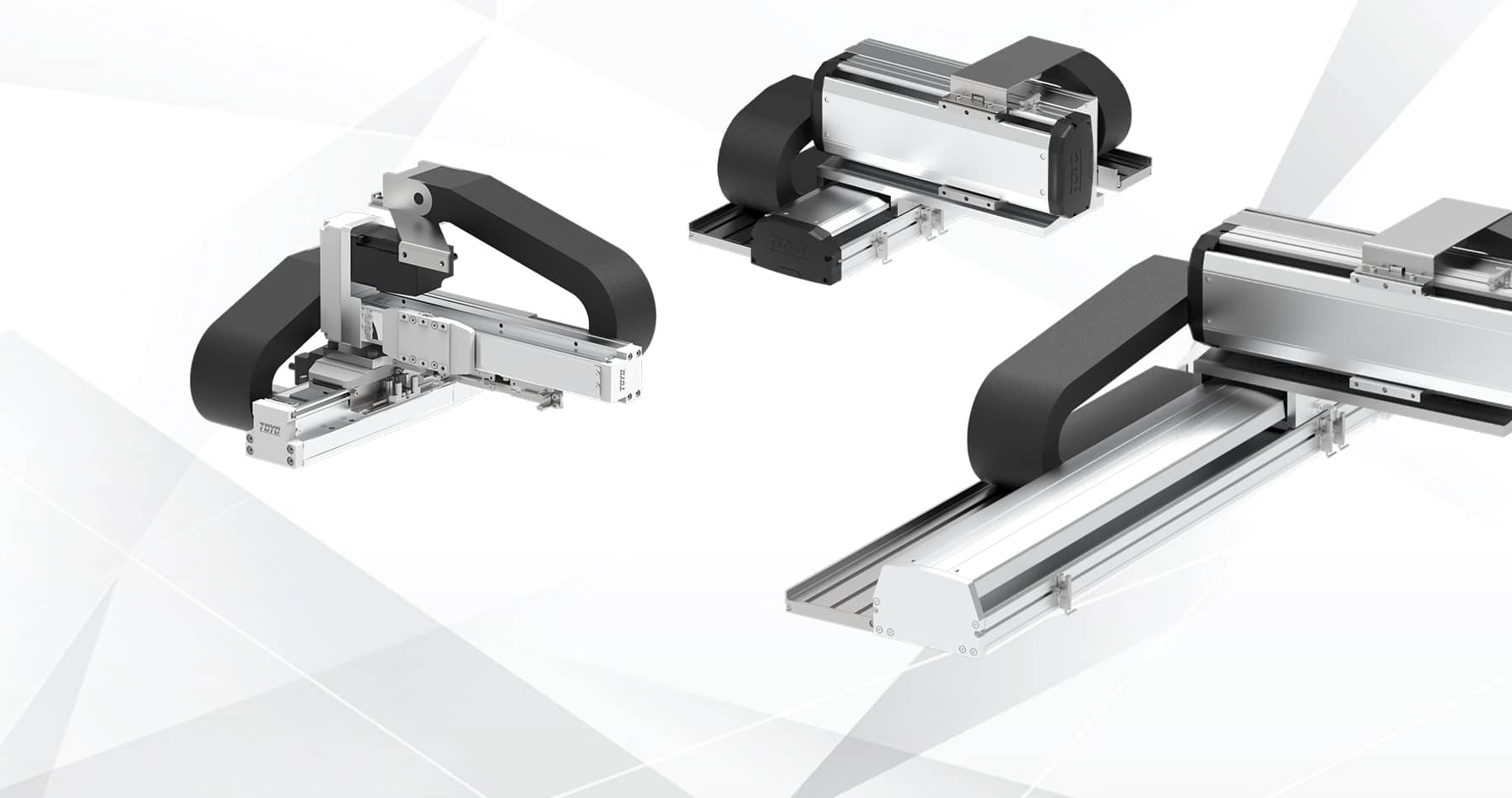
Multi-Axis Robots
Multi-axis robots, also known as Cartesian robots, enable precise movement across two or more axes within a single integrated system. Designed for complex positioning, interpolation, and coordinated motion, they are widely used in automation, handling, and assembly applications where accuracy and repeatability are critical.
Rectangular working area, metres across, real payload — that’s where an arm runs out and a gantry doesn’t. Envelope set by stroke rather than reach, stiffness from the frame. XYTH for ball screw accuracy, XYTB for belt speed over longer travel, XYGT for stiffness under load, supplied as one specified machine. Send us the envelope, payload and cycle time and we will configure it.
-

XYTH Series
Configurable ball screw XY and XYZ platform, with rotary and dual-axis layouts. For dispensing, inspection and pick-and-place where accuracy across the working area matters. -
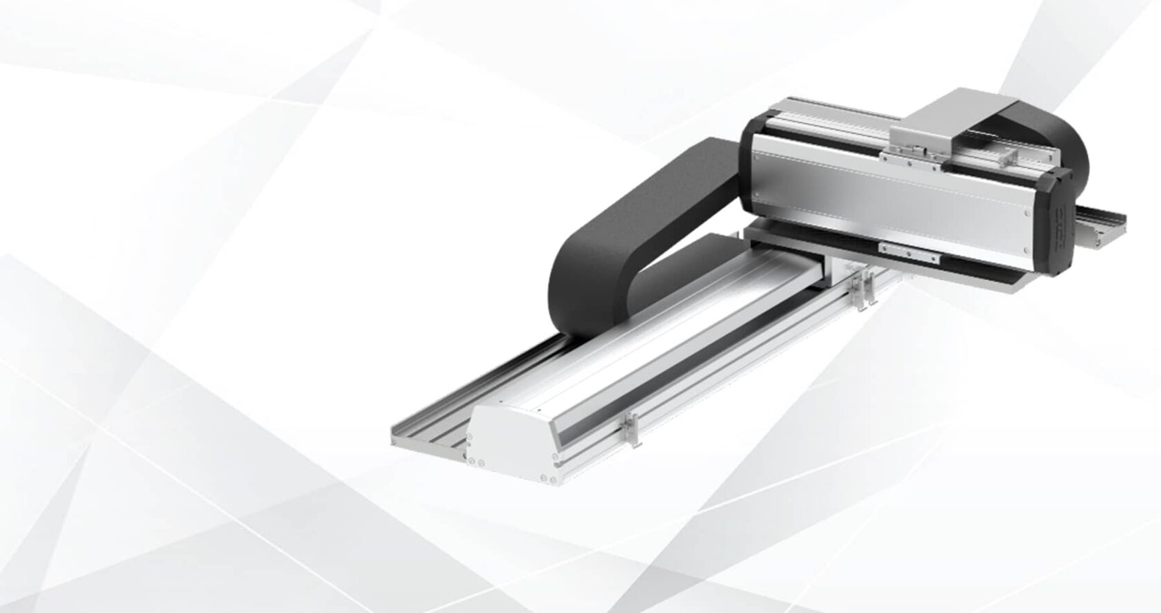
XYTB Series
Belt-driven XY and XYZ platform for speed over longer travel. For transfer, pick-and-place and handling across a larger working area. -
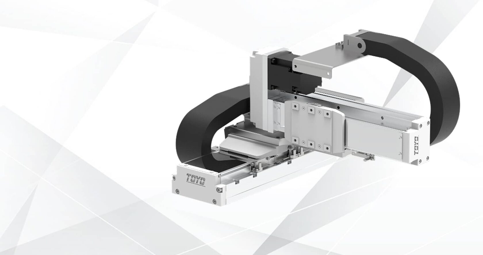
XYGT Series
XY and XYZ platform built on an integrated LM guide and ball screw, for stiffness under load. For tooling that carries offset mass or process force.
Supply and specification
Systems are supplied as a specified machine — axes, geometry and ratings defined as an assembly — with the drive and control architecture agreed against your platform. If you only need the mechanical module to design into a machine of your own, that is XY tables and multi-axis actuators.
Cartesian against SCARA and six-axis
Cartesian takes it when the working area is rectangular, when the payload is significant, or when the span runs to metres. A gantry covers ground no articulated arm can reach, and it does so with a stiffness an arm cannot hold at full extension. SCARA is faster for small, high-rate placement inside a compact circular envelope. A six-axis arm earns its place when the tool has to arrive at an angle or reach around the part. Flat, long or heavy points to cartesian, and it is usually simpler to guard and to program as well.
Sizing and integration
- Working envelope and anchoring. Travel in each axis, and whether the frame is floor-standing, bench-mounted or overhead. The mounting arrangement changes the structural specification as much as the strokes do.
- Payload at the tool point. Product, gripper, camera, cabling, and any process reaction force. The base axis carries all of it at an overhang that varies through the stroke.
- Cycle time drives the architecture. The move profile decides drive type per axis — belt for span and rate, ball screw for accuracy, thrust and vertical holding. Most systems use both.
- Accuracy at the process. Error stacks across axes and orthogonality contributes as much as axis repeatability. Quote us the tolerance on the finished part.
- Control architecture. Whether the axes run from your PLC, a dedicated motion controller, or a robot controller — and whether interpolation is required across them — shapes the drive specification and the commissioning effort.
- Cable management and end effector interface. Carrier routing across the moving joints, plus air, vacuum and signal to the tool, is where most gantry designs run into trouble late.
- Environment. Cleanroom, dry room or open shop floor. Sealed cleanroom axes can be specified throughout where particulate control applies.
Where these systems run
Pick and place between conveyors, trays and machines. Machine tending across several stations from a single overhead axis. Adhesive, sealant and solder paste dispensing along a programmed path. Automated optical inspection and measurement. Screwdriving and assembly cells. Palletising and end-of-line packing. Laser cutting, marking and routing gantries. EV battery module and pack handling, where payload and span both rule out an arm. Semiconductor, photonics and laboratory automation built from sealed axes. Benchtop systems for dispensing, test and small-part handling where floor area is the constraint.
Engineering notes
Well beyond an arm’s reach. Belt axes give over 3,000 mm of travel, and rack and pinion reaches 5,700 mm as standard with joinable rack sections past that. A gantry spanning several machines is a routine specification rather than a special case.
It depends on the axis combination, the span and the structure it is mounted to. Accuracy at the tool point is quoted per configuration rather than as a headline figure, because at these travels the frame contributes as much as the axes do.
Systems can be specified motorless for you to drive from your own servos and PLC, or with motors and drives specified to match your platform. Machine builders generally take the first, end users the second. Either way the drive specification is agreed before the order, not after it.
Yes, either mechanically coupled or electronically geared through the drives. Which is appropriate depends on the span, the racking loads and your control platform the two have quite different commissioning and fault behaviour, so it is worth settling early.
Working envelope, payload with tooling geometry, cycle time, required accuracy at the process, control platform, mounting arrangement and environment. Send that over and you get a specified configuration back rather than a product list.


Multi Axis Robot Solutions Tailored to Meet Your Requirements
Contact our team to understand how TOYO UK can meet your exact requirements, discuss our various products and how we can manage your actuator needs.