
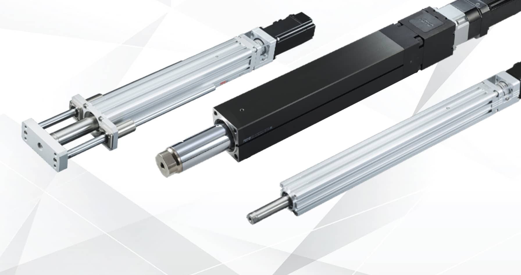
Rod Type Actuators
Rod type actuators provide compact, push-and-pull linear motion using a motor-driven screw and extending rod mechanism. They are commonly used where space is limited and simple, reliable linear movement is required for lifting, positioning, and adjustment applications across automation and machinery.
Programmable position, speed and force where a cylinder gives you two end stops. 50 to 800 mm of travel, to 40 kg, repeating to ±0.01 mm. Y, YH95 and the compact GTY. Press-fit and precision assembly, medical and lab equipment, and any line taking the compressor off the cost base. Send us the duty and we will size it.
-
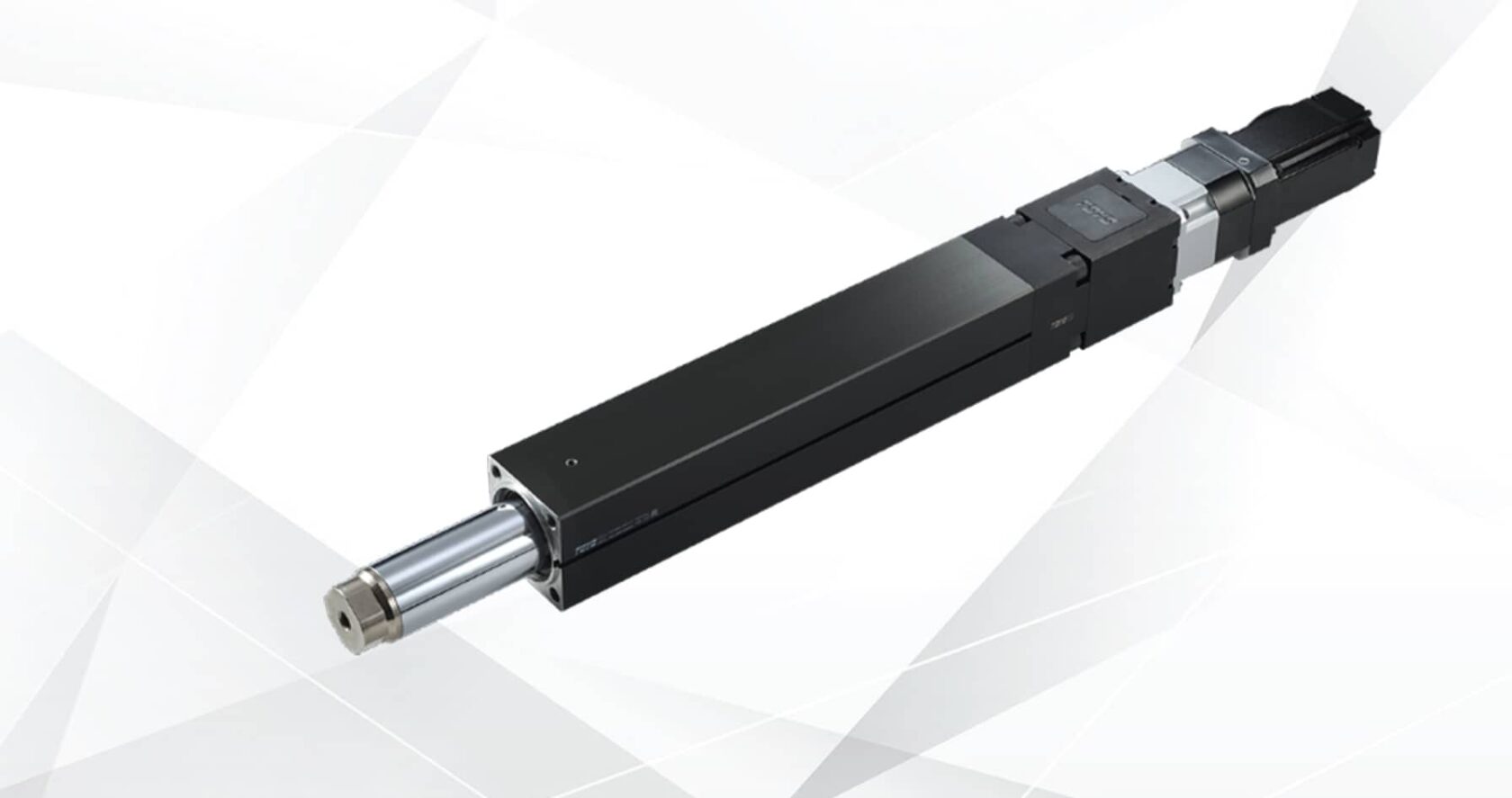
YH95 Series
Rod actuator for longer strokes, to 800 mm, taking motors from 100 W to 750 W. For press-fit, insertion and lift duty where a cylinder can’t control force or mid-stroke position. -
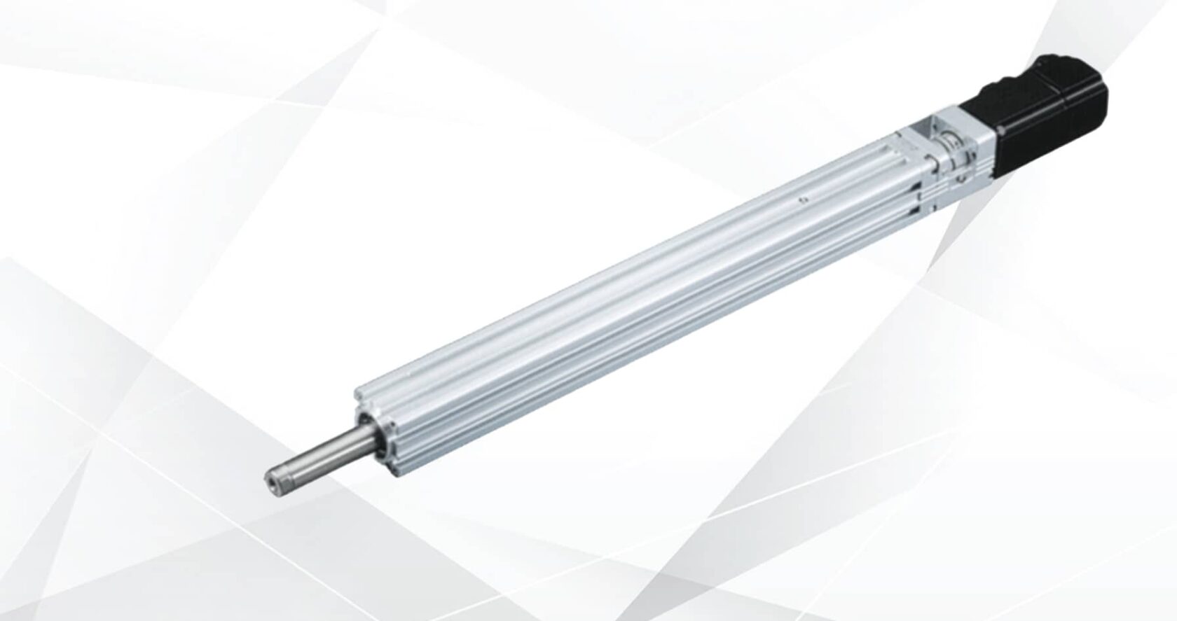
Y Series
Rod actuator to 600 mm of stroke and 40 kg payload, repeating to ±0.01 mm. The direct replacement for a pneumatic cylinder on clamping, indexing and positioning duty. -
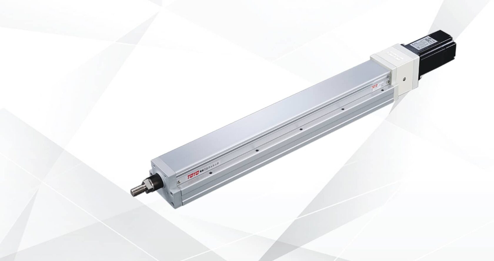
GTY Series
Compact rod actuator for tight envelopes. Programmable position, speed and push force in a small body, for medical, lab and small-assembly equipment.
Position and force control
Repeatability across the range is ±0.01 mm, with multi-point positioning and controlled push force as standard capability rather than an option. Where the requirement is to carry and guide a load across a distance instead of push along one line, a ball screw slide is the correct platform.
Supplied motorless, so the motor, drive and fieldbus stay on your existing platform; matched assemblies are on the integrated motor range. Non-standard strokes, rod ends and mounting arrangements are configured to order, with lead time confirmed against the specification.
Sizing and integration
- Thrust at the rod end, not payload. A press or clamp duty is sized on force and on how long that force is held. A transfer duty is sized on mass and profile. The two lead to different series and often different leads.
- Side load and guidance. Rod actuators take axial load. Anything cantilevered, guided off-centre or subject to a lateral reaction needs an external guide, or a slide-style axis instead — this is the most common cause of premature wear on a cylinder replacement.
- Retracted envelope. Overall length behind the mounting face is frequently the binding constraint on a retrofit, more so than stroke. Check it against the frame before the bracket is designed.
- Duty cycle and holding. Continuous cycling generates heat in the screw and nut. A long clamp hold at force is a thermal question for the motor, not a mechanical one for the actuator — give us the dwell as well as the rate.
- Force control architecture. Push-to-force needs current or torque limiting in the drive, so the capability sits partly in the servo and its configuration. Worth settling at the same time as the actuator, not afterwards.
- Vertical and suspended loads. The screw resists back-driving; a holding brake is still specified on anything suspended or safety-related.
Where these axes run
Press-fit and component insertion with force monitoring. Clamping and jig actuation on assembly cells. Indexing and lift between stations. Gauging and functional test rigs. Tool and guide adjustment on changeover, where a servo position replaces a manual setting and a written procedure. Diverter and gate actuation on high-rate conveying. Medical, diagnostic and laboratory equipment. Compressed-air reduction programmes, where the cylinders that need position or force control are converted first and the simple end-to-end ones are left alone.
Engineering notes
Sometimes, but it is not safe to assume. Mounting centres, rod end thread, and overall retracted length all need checking against the cylinder being replaced. Send the cylinder part number and the mounting arrangement and we will tell you what fits and what needs an adaptor plate.
Through torque or current limiting in the drive, with the actuator sized so the required force sits comfortably inside its rating rather than at the top of it. If the process needs the force value logged per cycle, say so it affects the drive and feedback specification more than the actuator choice.
Minimal by design. Where a lateral reaction is unavoidable, specify an external guide or a guided rod arrangement. We would rather engineer that in than replace a bushing eighteen months later.
Yes, intermediate strokes, rod end variants and mounting arrangements are configured to order, with lead time confirmed against the specification.
Required thrust and stroke, mass and orientation, cycle rate and dwell, any side load, the mounting interface, and the servo platform in use. Send that over and you get a specified actuator back rather than a series list.


Specify Your Axis With The UK Team
Send us the stroke, payload, orientation and move profile, and we will come back with a sized axis and a lead time confirmed against the specification.